Rotational Dynamics Experiment
Introduction:
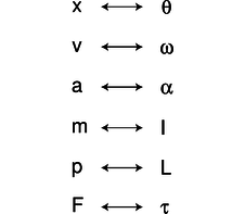
In this lab, we got to experiment with rotational dynamics. The definition of rotational dynamics would be; the study of forces and torques and their effect on motion, as opposed to kinematics (see ref. one). Instead of using the traditional symbols for velocity, acceleration, displacement, and theta; we use symbols for angular velocity, angular acceleration, and angular displacement. In this experiment we got to find the moment of Inertia of the rigid motor using masses, and measuring its parts geometry. Rotational motion is explained by Newton’s Second Law, and it states; the acceleration of an object is dependent upon two variables, the net force acting upon the object and the mass of the object (see ref. three)
Procedure
Determine the Rotor’s Moment of Inertia from Masses and Geometries.
Part 1
- First disassemble the rotor to measure the individual parts/components.
- Measure/ weigh each part of the rotor as necessary
- For any parts that can’t be weight directly, analyze its dimensions/density to figure out the mass.
- Reset the rotor, and the blocks in original position after measuring.
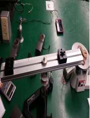
- Take a picture or memorize how the rotor apparatus appears so that when conducting part 2 the experiment is set up in the exact same way with the parts in the same position for part 1.
Part 2
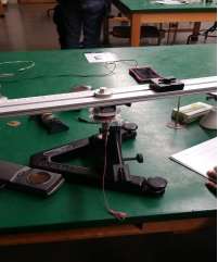
- Check to make sure the rotor apparatus is set up in the same order as it is in part 1 and the components are in the same position.
- Put the rotor apparatus near the edge of the table so the weights dont hit the table, begin to level the rotor apparatus by using the carpenter level.
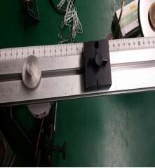
- Spool the string around the rotor being careful not to let rope overlap the rotor cylinder.
- Attach paper clips to the end of the string so the platform will move with constant velocity when pushed slightly.
- After enough paper clips are added, use the triple beam to weigh the mass of the paper clips.
- Since the CBR is only accurate at distances greater than 0.5 meters, the CBR must be arranged that distance or greater from the platform so it can record the motion as the platforms makes a lap around.
- Now spool up the string, make sure there are no overlaps and attach the .05 kg weight hanger to the string.
- Set up the TI-84 and the CBR
- Let the weighted hanger fall at the same time that you begin the CBR in order to record the data points. Now repeat these steps for your different weights 0.100kg, 0.150kg, 0.200kg, and 0.250kg
Method/ Theory:
The very first step in this experiment was to find the moment of inertia. The equation for inertia of a rigid body would be;
I = 
Each part of the body was divided into different parts. Measuring the mass of each and multiplying it to the position vectors of each. By applying Newton’s Second Law we get this equation;


Equipment:
1 Rotor Apparatus
1 TI-CBR ( Calculator Based RANGER [Sonic Motion Detector])
1 Triple Beam Balance
1 Vernier Caliper
1 Meter Stick
1 Set of Weights
1 TI 83 calculator
1 Carpenter’s Level
References:
- Dynamics (mechanics). (2014, November 18). Retrieved November 21, 2014, from http://en.wikipedia.org/wiki/Dynamics_(mechanics)
- Serway, Chapter 10, (rotational motion), sections 10.1-10.6
- Newton’s Second Law. (n.d.). Retrieved November 21, 2014, from http://www.physicsclassroom.com/class/newtlaws/Lesson-3/Newton-s-Second-law
- Ellis, Steven L. “Experiment 5 Rotational Dynamics.” Labatory Manual. University of Kentucky, department of Physics and Astronomy Physics 241. Fall 2011
Group Meetings:
|
11/9/2014 4:30 PM – 6:20 PM |
Performed Part 1 of Rotational Dynamics |
|
11/9/2014 Directly After Lab |
Our first group meeting was on the day of our lab. We met right after our lab was completed to discuss each member’s role in the lab report/experiment. We discussed how we were each going to do our parts. |
|
11/18/2014 4:30 PM –6:20 PM |
Performed Part 2 of Rotational Dynamics |
|
11/18/2014 Directly After Lab |
On this day we discussed work that had been completed thus far for Part 1 and analyzed our data according to the purpose of the experiment. We checked to make sure each member had done what they were expected to do. |
|
11/28/2014 6:00 PM |
On this day we discussed the changes that needed to be made in order to ensure that we correctly fulfilled the requirements of this lab. Our rough draft was due on December 2 nd, |
|
12/3/2014 After talking to the TA 1:00 PM |
On this day our group looked over the corrected rough draft and made changes and improvements for our final. Our Principal investigator and skeptic worked together through email in order updates the results and conclusions |
Data & Calculations
Mass and Geometric calculations
Equ (1): 
Equ (2): 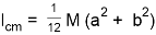 (Inertia of a rectangular plane where a is the length and b is the width)
Equ (3):  (Inertia of a solid cylinder with an axis through the center with the radius = R)
The chart1 below shows the object mass, the distance from the center, the dimensions and inertia. Chart1 shows the total inertia when all parts are combined

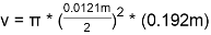
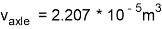
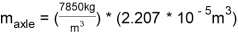
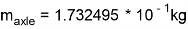
Since parts of the rotor apparatus where hard to find directly, the groups was able to use the find the mass using density and objects dimensions. An example of this was the central axle, in which the group used its density to identify its mass. Here is a sample calculation below.
After measuring the dimensions of the central axle the group got 0.192m by 0.0121m diameter
formula: 
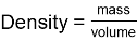
The density of steel was used to calculate the mass of the central rod . Steels density is 7.85g/
mass = (density)X(volume)
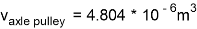
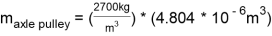
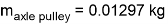
The same process was used to figure out the mass of the axle pulley. The small holes in the axle pulley would create an insignificant difference in the inertia, we decided to consider the pulley to be a solid cylinder to simplify calculations . The same equations were used to find the volume of the axle pulley.
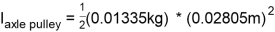
The diameter of the axle pulley was 0.0562m and the height was 0.001m
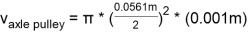
This axle pulley is has a density of 2.70 g/since it is made of aluminum
I can now be calculated using the geometric equations from above since we know the dimensions and the masses of the components for the rotor apparatus.
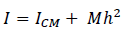
For this part of the calculation, this equation was used
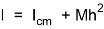 , h = distance from center
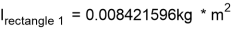
The I of the rectangles is calculated using the equation 2 from above which is:
Rectangle 1:

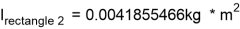
Rectangle 2:

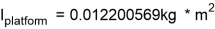
Platform:

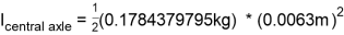
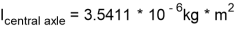
Central Axle:
The equation 3 will be used for the central axle to solve for  .
.
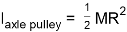
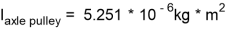
Axle Pulley:
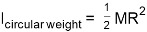
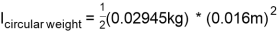
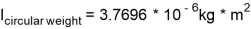
Circular Weight:
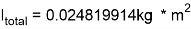
Total Inertia:
Adding all the component inertia sums up to:
Method Cont.:
After calculating the necessary values for inertia, we then proceed to step two of the experiment, where we use the CBR devise to calculate rotational dynamics.
|
Table 1: Frictional Torque |
||
|
M (kg) |
Ft (N) |
τ =RaxleFt (Nm) |
|
0.0231 kg |
0.225918 N |
2.711 E-3 |
In table 1, we first weight the amount of paper clips used, which we got 0.0231 kg. Then we used Newton’s Second Law to find Ft .
Ft = mg = (0.0231 kg) * (9.78 m/s^2) = 0.225918 N
τ =RaxleFt (Nm) = (0.012 m) * (0.225918 N) = 2.711 E-3 Nm
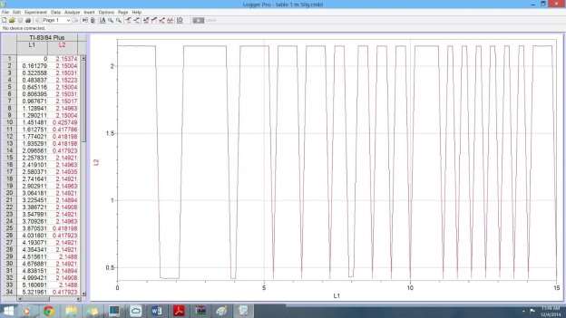
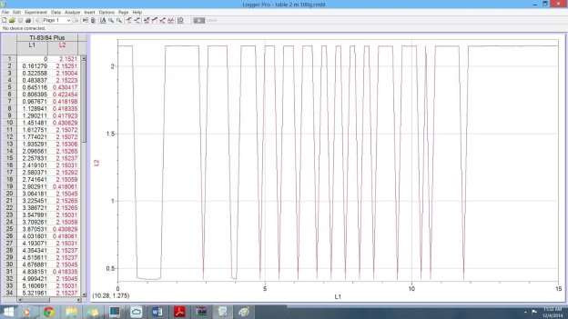
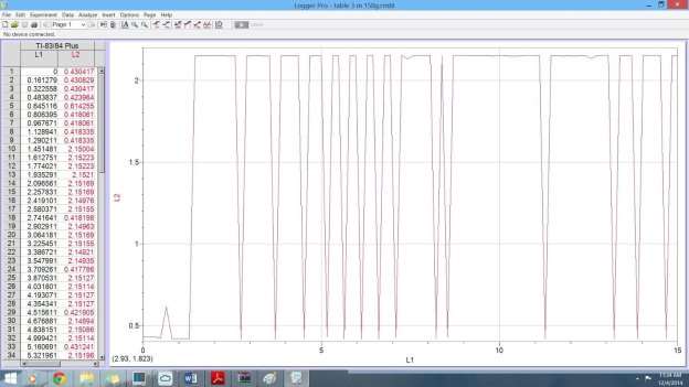
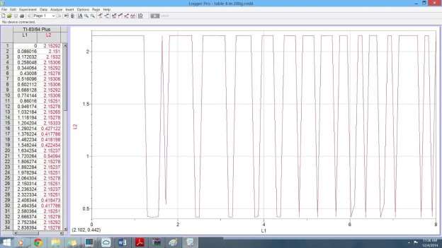
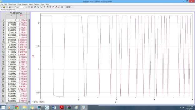
Table 2 through table 6 shows the values of time for t , t
, t and t
and t (results are from the CBR; when using (x) mass.)
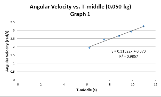
Table 2: Hanging mass = 50g
|
t |
t |
t |
T [s] |
ω [rad/s] |
|
|
1 |
1.26 |
3.70 |
5.14 |
3.88 |
1.619 |
|
2 |
3.70 |
5.14 |
6.14 |
2.44 |
2.575 |
|
3 |
5.14 |
6.14 |
7.10 |
1.96 |
3.206 |
|
4 |
6.14 |
7.10 |
7.73 |
1.59 |
3.952 |
|
5 |
7.10 |
7.73 |
8.52 |
1.42 |
4.425 |
|
Slope = α |
0.31322 |
[rad/s |


 ]
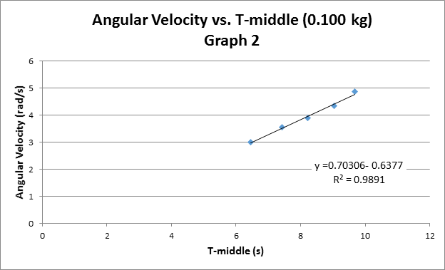
]Table 3: Hanging mass = 100g
|
t |
t |
t |
T [s] |
ω [rad/s] |
|
|
1 |
2.73 |
3.70 |
4.65 |
1.92 |
3.272 |
|
2 |
3.70 |
4.65 |
5.30 |
1.6 |
3.927 |
|
3 |
4.65 |
5.30 |
5.96 |
1.31 |
4.796 |
|
4 |
5.30 |
5.96 |
6.61 |
1.31 |
4.796 |
|
5 |
5.96 |
6.61 |
7.07 |
1.11 |
5.661 |
|
Slope = α |
0.7036 |
[rad/s |

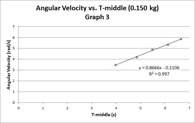
Table 4: Hanging mass = 150g
|
t |
t |
t |
T [s] |
ω [rad/s] |
|
|
1 |
3.55 |
4.34 |
5.00 |
1.45 |
4.333 |
|
2 |
4.34 |
5.00 |
5.47 |
1.13 |
5.56 |
|
3 |
5.00 |
5.47 |
5.97 |
0.97 |
6.478 |
|
4 |
5.45 |
5.97 |
6.44 |
0.97 |
6.478 |
|
5 |
5.97 |
6.44 |
6.94 |
0.97 |
6.478 |
|
Slope = α |
0.8666 |
[rad/s |
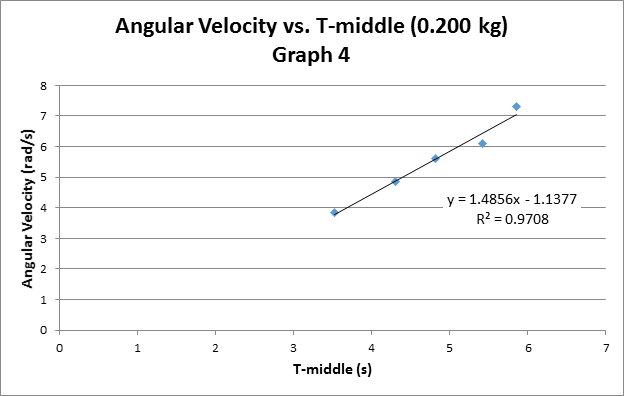
Table 5: Hanging mass = 200g
|
t |
t |
t |
T [s] |
ω [rad/s] |
|
|
1 |
2.318 |
3.095 |
3.684 |
1.366 |
4.5997 |
|
2 |
3.095 |
3.684 |
4.202 |
1.107 |
5.676 |
|
3 |
3.684 |
4.202 |
4.734 |
1.05 |
5.686 |
|
4 |
4.202 |
4.734 |
5.166 |
0.964 |
6.518 |
|
5 |
3.684 |
5.166 |
5.583 |
1.899 |
3.309 |
|
Slope = α |
1.4856 |
[rad/s |
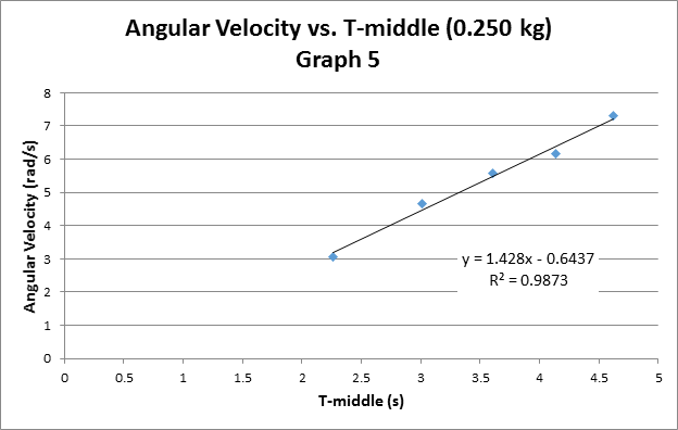
Table 6: Hanging mass = 250g
|
t |
t |
t |
T [s] |
ω [rad/s] |
|
|
1 |
2.153 |
3.016 |
3.612 |
1.459 |
4.307 |
|
2 |
3.016 |
3.612 |
4.123 |
1.107 |
5.676 |
|
3 |
3.612 |
4.123 |
4.547 |
0.935 |
6.72 |
|
4 |
4.123 |
4.547 |
4.993 |
0.87 |
7.22 |
|
5 |
4.547 |
4.993 |
5.338 |
0.791 |
7.94 |
|
Slope = α |
1.428 |
[rad/s |
In the previous tables T was calculated as  . Omega calculated as;

Logger Pro Data
torque calculations table:
Table 7
|
Hanging Mass [kg] |
F |
τ =RaxleFt (Nm) |
α [rad/s |
|
|
1 |
0.050 |
0.489 |
5.868 E-3 |
0.31322 |
|
2 |
0.100 |
0.978 |
0.011736 |
0.7036 |
|
3 |
0.150 |
1.467 |
0.017604 |
0.8666 |
|
4 |
0.200 |
1.956 |
0.023472 |
1.4856 |
|
5 |
0.250 |
2.445 |
0.02934 |
1.428 |
|
Slope = I = 0.0234kg/m2 |
Intercept = τfric 0.001 = Nm |
 = mg [N]
Table 8 shows the moment of inertia of each component and the total inertia.
|
Table 8: Moment of Inertia Data |
Self Constructed |
|
Component |
Inertia [kg/m |
|
Rectangle 1 |
0.008421596 |
|
Rectangle 2 |
0.0041855466 |
|
Platform |
0.012200569 |
|
Central axle |
3.5411 E-6 |
|
Axle pulley |
5.251 E-6 |
|
Circular weight |
3.7696 E-6 |
|
Total inertia |
0.024819914 |

Discussion & Analysis
Sources of Error
Every experiment tends to have its uncertainties when measuring in the laboratory. Using these uncertain measurements creates uncertainties in the final results of the lab. These uncertainties in experiments can stem from measurements taken as well as our tools used. The errors are associated with our measurements taken. Included would be the length and mass measurements. These errors lead to our calculated moment of inertia values to have uncertainties. Even the CBR used in the experiment caused uncertainty in our final results and conclusion.
These errors for the experiment were
±0.0005 m for measurements taken using the measuring tape which includes the changes in width,length, and height.
±0.00005 g for measurements taken using the triple beam balance such as the change in mass.
Propagation error
For the first part of the experiment the moment of inertia for the system was calculated. In order to do this the components of the system inertia was added up. The individual parts included were the circular weight, the platform, the central rod, and the axle. The screw attached was neglected in this experiment. These components each had uncertainty associated with them which led to uncertainty in the final calculation of the moment of inertia.

We broke this equation up into each individual moment of inertia for each object and solved for the total error.
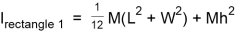
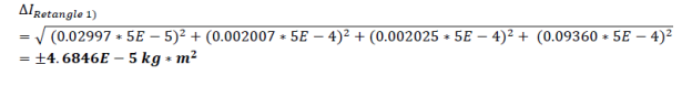
Rectangle 1
Formula:
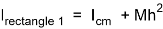
W = Width
L = Length
M= Mass
h = distance from rotation
The propagation of error for  , the partial derivatives for given equation for W,M, L, and h.

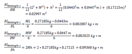
The propagation of error for the rectangle’s moment of inertia is found by solving for these values above and plugging them into the general formula below.

Next pluggin in the values above we get:
Rectangle 2
This same process was carried out for 2nd rectangle since it has the same formula for moment of inertia as the first one.
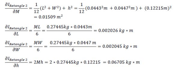
The propagation of error for the rectangle’s moment of inertia can be determined by solving for these values above and plugging them into the general formula below.
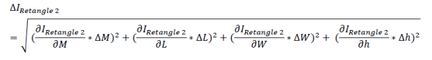
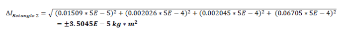
Plugging in the values above we get:
Circular Weight
For the circular weight we use the formula:
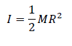
Where,
M= Mass
R= Radius
To find the propagation of error for I we used the partial derivatives of the given equation for M and R.
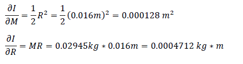
The propagation of error for the rectangle’s moment of inertia can be determined by solving for these values above and plugging them into the general formula below.
Cite This Work
To export a reference to this article please select a referencing stye below:
Reference Copied to Clipboard.
Reference Copied to Clipboard.
Reference Copied to Clipboard.
Reference Copied to Clipboard.
Reference Copied to Clipboard.
Reference Copied to Clipboard.
Reference Copied to Clipboard.